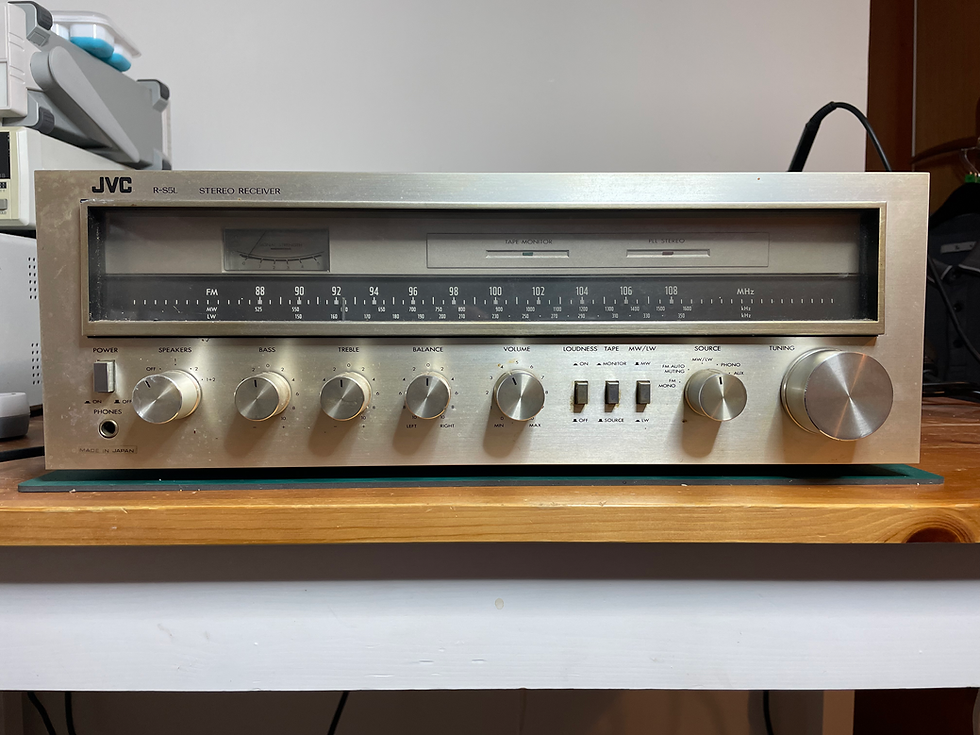
JVC RS5L
- sinbadcarey
- Sep 30, 2025
- 1 min read

This is a lovely classic receiver from 1979 and was sold to me by a chap who was clearing out his late father’s shed. Generally speaking, it’s in quite good condition and after completing an FTR, the following issues were found:
Rusty metal case lid
Needs a deep clean inside and out
Right channel has no output
Failed and leaking electrolytic capacitors (replaced to progress testing)
Controls all very noisy
Tuning has a clunk when changing direction
DC offset on left channel too high at 22mv
Drawing too much standby power
My plan is to address the issues, bring this back to full working order and then restore it back to like new condition with new capacitors and a Bluetooth module.


After a good clean with IPA and a stiff brush, I’ve managed to remove all of the gunk. I took C801 and C802 out which are the large smoothing caps and there’s sign the rubber bung at the base of each one is compromised, so that’s probably where all the gunk has come from, although they do test as working still so I’ve put them back for now. The other smaller caps in front of them, C707 which is tied across the positive and 0V rails & C901 which is concerned with what looks like current regulation for the negative power rail are both obviously defective so I remove them and replace with temporary ones I have in stock, as…
On my first inspection of the internals there are some electrolytic caps which have leaked their contents all over the PSU and output stage PCB and possibly damaged some other ceramic disc caps too, but aside from needing a really good clean everything seems to be in good condition and complete. My first job will be to clean up the mess and remove and test the electrolytic caps in that area.
Before I do anything I want to power it up through the dim-bulb and check its condition. Everything looks good with the display lighting up, although the dim-bulb is glowing slightly which Isn’t great as it means the receiver is drawing more power than it should. When I touch the output transistors heatsink, I can feel the right side of it is warm too, so it looks like something is not right. Measuring for DC offset at the output shows the left channel as having 22mv and the right at 0 mv, which doesn’t bode well!